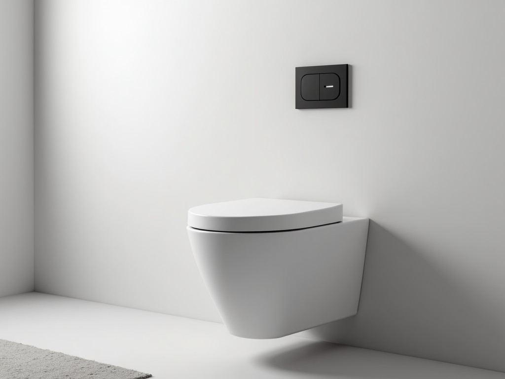
Factory Supply Space Saving Wall Hung Toilet
Factory Supply Space Saving Wall Hung Toilet
Overview
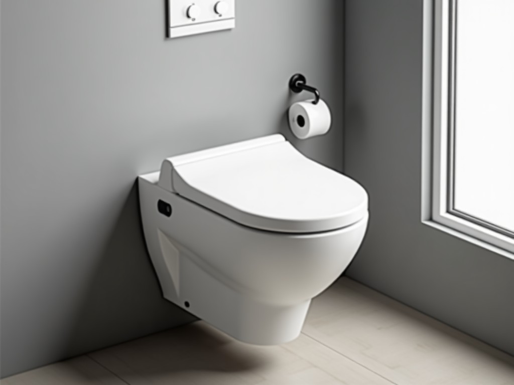
Wall hung toilets are selected in industrial facilities where floor space is limited and cleaning efficiency is a priority. By mounting the fixture to a concealed support frame, the floor area beneath the bowl remains unobstructed, allowing for easier mopping and reducing the accumulation of debris around the base.
Technical Specifications
| Parameter | Typical Value |
|---|---|
| Overall Height (including seat) | 380 mm |
| Bowl Width | 360 mm |
| Bowl Depth from Wall | 520 mm |
| Flush Volume (dual‑flush) | 4.5 L / 3 L |
| Material | Vitreous china, compressive strength > 30 MPa |
| Maximum Static Load on Frame | 400 kg |
| Required Water Pressure | 0.1–0.5 MPa |
| Rough‑in Distance (center of outlet to finished wall) | 180 mm ± 5 mm |
Design Features
- Concealed steel support frame with adjustable brackets accommodates wall thicknesses from 100 mm to 150 mm.
- Rim‑less bowl design eliminates hidden cavities, simplifying disinfection and reducing bacterial harborage sites.
- Soft‑close seat mechanism minimizes impact noise and extends seat lifespan in high‑traffic areas.
- Integrated anti‑siphon valve prevents backflow contamination under fluctuating supply pressure.
- Surface finished with a nano‑silicate glaze that resists staining and chemical attack from cleaning agents.
Applications in Industrial Settings
Factories, workshops, and warehouses often require sanitary fixtures that do not impede workflow or cleaning routines. The wall hung configuration leaves the floor clear for automated guided vehicles, pallet jacks, and routine scrubbing, thereby reducing the time spent maneuvering around protruding bases. Additionally, the elevated position minimizes the risk of water pooling on the floor, which can create slip hazards in environments where oils or coolants are present.
Installation Requirements
A load‑bearing wall or a purpose‑built steel stud framework must support the frame’s rated load. The installer should verify that the wall can resist a minimum shear force of 2 kN at the mounting points. Water supply lines should be terminated with a ½‑inch shutoff valve located within 300 mm of the inlet, and the waste outlet must connect to a 100 mm PVC trap with a minimum slope of 2 % toward the main drain.
Quality Control Philosophy
Each unit undergoes dimensional verification using a coordinate measuring machine with a tolerance of ±0.5 mm on critical interfaces. The glaze is inspected for uniformity under 45 ° illumination to detect pinholes or thin spots that could compromise chemical resistance. Load testing of the support frame is performed at 125 % of the rated static load for a duration of five minutes to confirm elastic recovery without permanent deformation.
Customization Options
Clients may specify alternative seat materials such as polypropylene with antimicrobial additives or stainless‑steel hinges for corrosive atmospheres. Flush mechanisms can be adjusted to deliver a reduced volume of 3 L for low‑flow requirements while maintaining effective trap clearance. Frame finishes are available in powder‑coated gray or zinc‑plated variants to match existing structural elements.
Frequently Asked Questions
What information is needed to obtain a quotation?
Provide the wall material and thickness, required flush volume, any special seat or hinge specifications, and the projected quantity. This enables the engineering team to confirm frame compatibility and finalize pricing.
Can the rough‑in distance be altered?
The standard rough‑in is 180 mm, but custom brackets can shift the outlet by up to ±20 mm to accommodate non‑standard stud layouts. Confirmation of the exact dimension is required before frame fabrication.
How is the product protected during export shipment?
Each toilet is packed in a double‑wall corrugated crate with corner protectors and a polyethylene moisture barrier. The frame is immobilized with foam blocks to prevent shifting, and the crate is sealed with strapping that meets ISTA‑3A performance standards.
Contact for Inquiry
To discuss technical details, request a CAD model, or receive a formal quote, use the inquiry link below. Our engineering team will respond with the necessary documentation within two business days.
Request Technical Quote